Hardware filters and amplifiers
So you now have an analog signal on some GPIO pin, but how to go from that to live stage performance? This page shows some useful hardware circuits to help you get started.
But first things first:
Do I need amplification?
Maybe all you want to drive is a headphone. Can you connect it, directly? The answer depends on the MCU you use, but before jsut trying, you should connect two problems:
- First, MCUs differ on how much current they can provide on the GPIO pins. For instance, the pins on a classic Arduino Uno are rated at 40mA maximum current, but this value will be much lower on an ESP8266, for instance. Trying to draw too much current could result in damaging the pin.
- Second, the speakers in a headphone will generally be a coil, which is an “inductive load”, which means switching them on and off may result in surprising voltage peaks, which - again depending on your MCU - could damage the GPIO pin, even without exceeding the current rating.
Thus, in general, the safe choice is to connect only a high impedance output circuit. This could be as simple as an active speaker, a headphone amplifier, or simply a line input.
That said, however, connecting a headphone, directly (or through a simple resistor), will work in many cases. Mozzi contributors have done that many times, and there’s even an official Arduino tutorial suggesting to connect a headphone directly to a GPIO pin of an Arduino Uno R3. If your board wasn’t too cheap, and/or you want to make sure it will continue working long term, amplification is certainly recommendable.
Do I need filtering?
That’s up to your own ears, but - not trying to insult your age - you may also want to have your children listen. Esp. PWM and PDM output modes may contain artifacts in the form of a high frequency hiss at the carrier frequency, which is usally not audible to adults, but - depending on the configuration - may be to kids or pets. This can be easily addressed in a hardware filter.
Filtering circuits
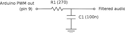
Low pass audio filter
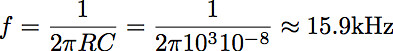
Here’s some info about low pass RC filters and a calculator to help choose components. For Mozzi, an RC filter with a roll-off frequency of just under 6kHz works well, using a 270 Ω resistor and a 100n capacitor, as shown below.
Notch filter for 16384 Hz carrier frequency
First versions of Mozzi used a 16384 Hz PWM carrier frequency on AVR CPUs (originally known as the “STANDARD” mode). This was soon doubled, but if you want to squeeze out a few % more CPU power, or you want to trade a lower frequency for a higher output signal resolution, you may once again end up with audible artifacts. In particular children will typically find a 16786 Hz carrier frequency irritating, while adults are often unable to perceive it at any level!
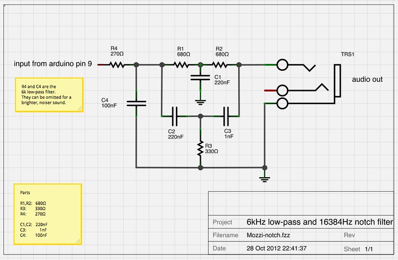
Many thanks to Andrew McPherson, who sent a schematic and equation for a twin-T notch filter which he used successfully to remove the offending 16384 Hz frequency.
Here’s a design tool for calculating Twin-T notch filters.
Andrew also reported that the low-pass and notch filter described here can be used together in series without any problems.
Here’s a schematic for the 6kHz low pass and the notch filter using commonly available parts chosen to exactly match a 16384Hz carrier frequency, using the notch filter design tool.
More Advanced Filter with Volume control
Simple low-pass filtering is usually enough when outputting straight from chips without a DAC (Digital to Analog Converter), especially as they usually have a limited number of bit resolution (8 or the like).
However, more advanced outputting schemes, for instance with an audio DAC (usually 16bits), can greatly benefit more advanced filtering and power stabilization. This schematic is an example of such filtering. It implements a second order low-pass filter (which will attenuate more quickly frequencies beyond its cutoff than a first order) with stabilized audio-type operational amplifiers (TL074).
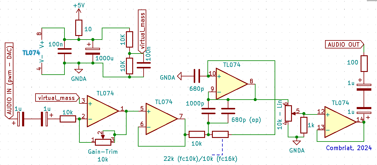
Quick functional description
Stabilization and virtual mass
The top left part of the circuit provides a clean voltage source from the 5V available on most boards. This is critically needed especially if you are powering the board via USB which is extremely noisy. This filtered 5V is used to power the Op-Amps. While we are at it, we create a virtual mass, at 2.5V. This is needed because the TL074 is not a rail-to-rail amplifier: it cannot provide voltages close to its powering values (+5V and GND here), especially towards GND. As signals created both by a DAC or PWM always have GND as the minimal value, part of the signal would be clamped by the amplifier, resulting in saturation. In order to resolve that, we are going to biased the signal to 2.5V which means that our waveform will be centered on 2.5V instead of having 0V as a lower value.
Bias and gain
The first stage after the AUDIO IN is taking care of biasing the signal at 2.5V. The first two capacitors are first removing the DC component of the signal which is then centered on 0V, and the OP-AMP biased it to 2.5V. This stage also comports a gain setting with the trimmer of 10k. The value of the trimmer should be adjusted at the end so that no saturation happens when sound is outputted by Mozzi. Filtering
The next two OP-AMP are performing a second order low-pass-filter on the signal, removing high frequencies (DAC stepping, EM noise). It cutoff frequency can be changed by the value of one resistor between 10kHz (22kOhm) and 16kHz (10kOhm). 10kHz is usually the good choice.
Volume
The last stage implements a simple volume control with 10k potentiometer (linear). The 1k resistor attached to it gives the potentiometer a response which is closer to a logarithmic potentiometer which may be harder to find. Of course a logarithmic potentiometer (without the additional resistor) does perfectly the job. This is followed by a simple buffer to bring down the output impedance. The output capacitors are there to remove the bias and give the next stage a signal centered on GND, which preferred in audio. Note on the DC capacitors
DC capacitors should normally be of non-polarized type. However, it can be hard to find non-polarized capacitors with values in the range of the microFarad (or expensive). The circuit here uses the trick that a couple of polarized capacitors, with reversed polarities behaves like a non-polarized capacitor. Of course, these can be replaced with a single, non-polarized one.